| Moddex Reference | Spec Detail | Application Process |
|---|---|---|
PC SYS 1 | Dulux Duralloy or equivalent - Standard PC finish https://duluxpowders.com.au/products/duralloy/ Note: Some colours may attract a surcharge | Whip blast, metaprep (primer for Gal) Zinc for black steel, Powder coat |
PC SYS 2 | Dulux Duratech or equivalent – Commercial Grade PC finish https://duluxpowders.com.au/products/duratec/ Note: Some colours may attract a surcharge | Same as above but using commercial grade top coat |
PC SYS 3 | Wet Spray 2 coat Paint System – Industrial/Mining Grade Paint System | Sand blast, 2 pack epoxy primer, 2 pack poly urethane. |
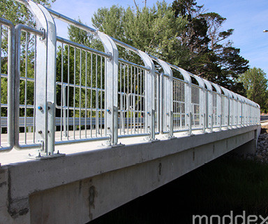
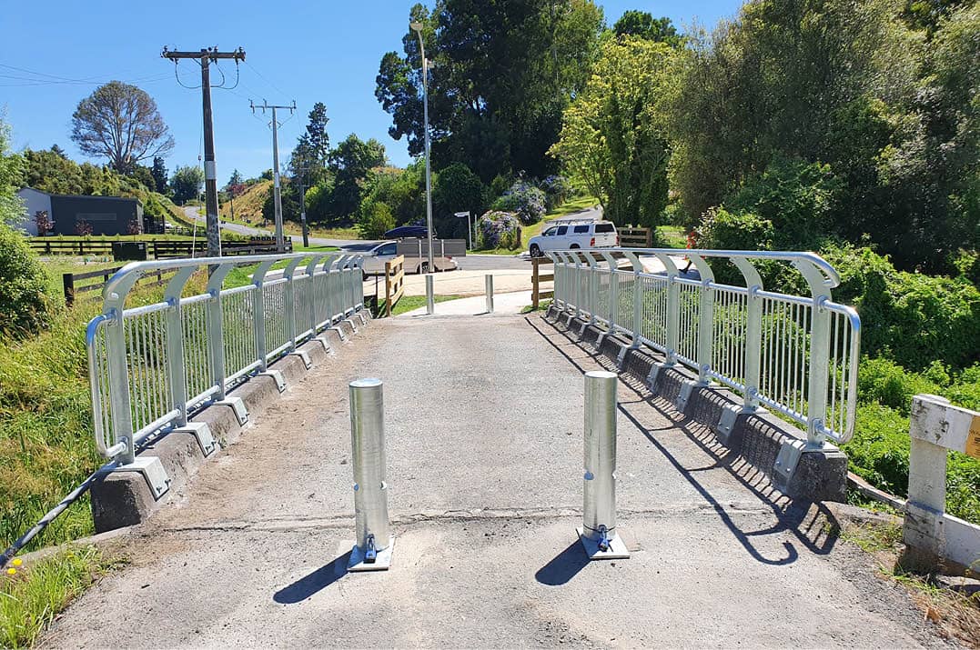
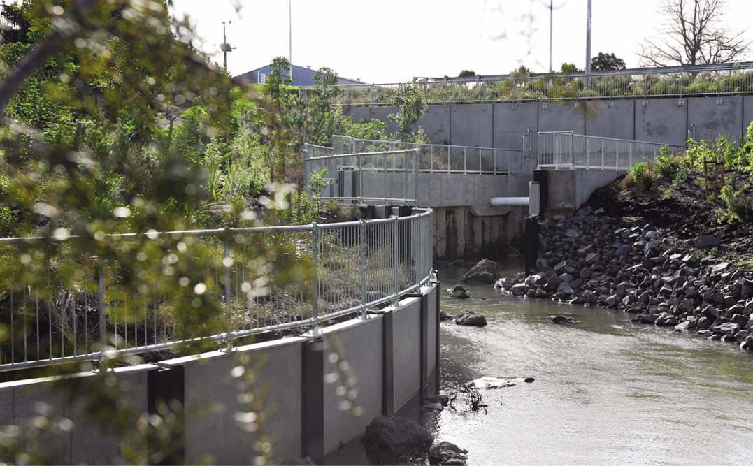
Bridge Barriers


Moddex proprietary BridgerailTM systems ensure balustrades on bridges can be specified and fitted effortlessly, with compliance guaranteed. This product is perfectly suited to public access areas forming part of road, rail or other elevated bridge structures.
Thanks to years of engineering expertise, Moddex pre-engineered designs are able to provide ultimate peace of mind to our Road and Rail Authorities, Consulting Engineers and Civil Contractors alike.
In stock now. Contact one of our Sales team today.
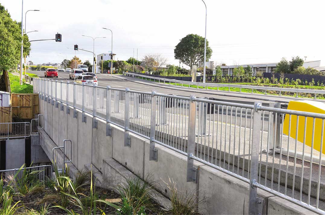
Compliant road and rail bridge barrier systems
Moddex has created this unique BridgerailTM system to comply with AS5100.2 Clause 12.5 and the NZTA Bridge Manual Compliant to Clause B6.4.*
BridgerailTM makes your transport infrastructure barrier systems seamless:
- Pre-fabricated kit-form systems allow for speedy installation
- No need for site welding – Modular assembly
- Tough and durable – BridgerailTM has a 100-year design life
- BridgerailTM is on average 30% faster to install than traditional pre-fabricated systems


Moddex Powder/Paint Coat Specification – Reference Charts
Configurations
View materials:
-
BR10AS5100.2 CL12.5 and NZTA Clause B6.4* Compliant Offset Cycle Rail Level - Standard 2.0 Mtr Spacing
-
-
-
-
-
BR40AS5100.2 CL12.5 and NZTA Clause B6.4* Compliant Balustrade Level - Standard 2.0 Mtr Spacing with Offset Cycle Rail
-
-
BR45AS5100.2 CL12.5 and NZTA Clause B6.4* Compliant Balustrade Level - Standard 2.0 Mtr Spacing with Offset Cycle Rail and Handrail
-
BR50AS5100.2 CL12.5 and NZTA Clause B6.4* Compliant Balustrade Level - Standard 2.0 Mtr Spacing with Offset Cycle Rail, Kerb Rail and Handrail
-
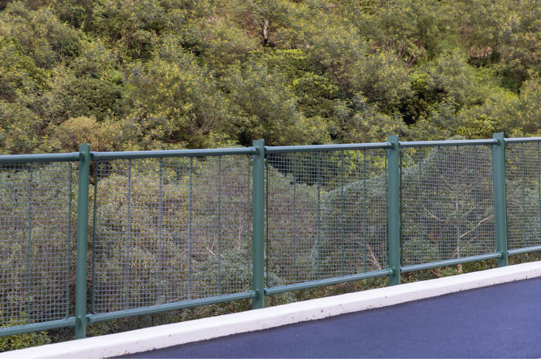
BR50MAS5100.2 CL12.5 and NZTA Clause B6.4* Compliant Balustrade Level - Standard 2.0 Mtr Spacing with Offset Cycle Rail, Kerb Rail and Handrail (with Mesh)
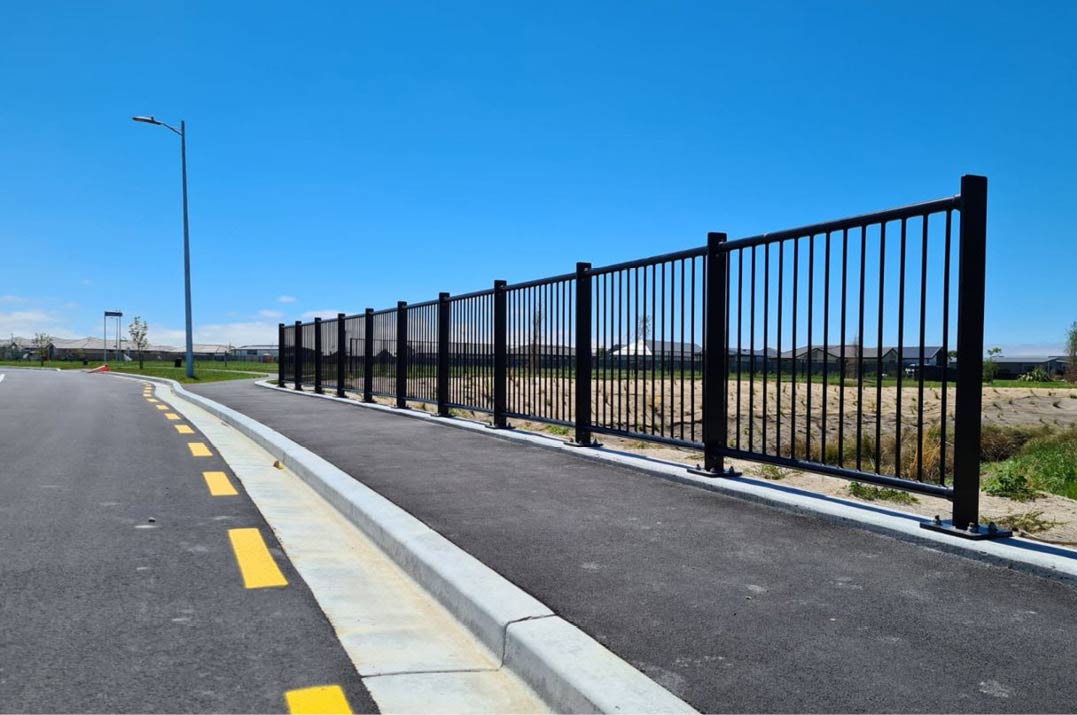
Applications
Easily configured to suit any application.
-
Cycle Bridges
-
Road Bridges
Compliance
To save you some time, we’ve included an extract from the Austroads Guide To Road Design for Australia, the Australian Standard Bridge Design and the NZTA Bridge Manual so you can see at a glance what is required to keep people safe in public areas.
Austroads Guide To Road Design; Part 6A
5.5.3 The installation of a fence at the side of a path used by cyclists is desirable where:
there is a steep batter or large vertical drop located in close proximity to the path
the path is adjacent to an arterial road and it is necessary wto restrict cyclist access to the road
a bridge or culvert exists on a path
a hazard exists adjacent to a particular bicycle facility
cyclists are likely to be ‘blazing a separate trail’ at an intersection between paths or around a path terminal.
Australian Standard Bridge Design; Part 2
This Standard was prepared by the Standards Australia Committee BD-090, Bridge Design, to supersede AS 5100.2—2004.
This Standard is also designated as Austroads publication AP-G51.2-17.
The objectives of the AS(AS/NZS) 5100 series are to provide nationally acceptable requirements for—
(a) the design of road, rail, pedestrian and cyclist path bridges;
(b) the specific application of concrete, steel, timber and composite construction, which embody principles that may be applied to other materials in association with relevant standards;
(c) the assessment of the load capacity of existing bridges; and
(d) the strengthening and rehabilitation of existing bridges.
The objective of this Part (AS 5100.2) is to specify minimum design loads and load effects for road, rail, pedestrian and cyclist path bridges, and other associated structures.
The requirements of the AS(AS/NZS) 5100 series are based on the principles of structural mechanics and knowledge of material properties, for both the conceptual and detailed design, to achieve acceptable probabilities that the bridge or associated structure being designed will not become unfit for use during its design life.
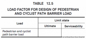
Clause 12.5 Pedestrian and cyclist path barrier load
Pedestrian and cyclist path barriers shall be designed for the most extreme of the following loads:
(a) A load of 0.75 kN/m acting on the longitudinal rail or the top of the barrier simultaneously in a transverse and vertical direction.
(b) A load of 1.0 kPa acting in a transverse direction on the total barrier infill area, whether comprising baluster, mesh or solid.
( c) A single load of 0.6 kN acting over an area of 0.1 m x 0.1 m in a transverse direction away from the path on the infill area, whether comprising baluster, mesh or solid,
(d) Forces from wind load, water forces and debris or earthquake.
The deflection of a pedestrian or cyclist path barrier subject to the serviceability loading (a) to ( c) above shall not exceed-
(i) for longitudinal members ………………………………………………………… L/800; and
(ii) for posts ………………………………………………………………………………… h/300,
where
L = span of member between posts
h = height of the post above the base plate
In addition to the provisions above, where the relevant authority specifies that the barrier is to restrain crowds or people under panic conditions, the barrier shall be designed for the most extreme of the following loads:
(A) A load of 3.0 kN/m acting in a transverse direction away from the path simultaneously with a vertical load of 0.75 kN/m acting on the top rail; or
(B) A load of 1.5 kN/m acting in a transverse direction away from the path simultaneously with a vertical load of 0. 75 kN/m on any one longitudinal member; or
(C) A load of 1.5 kPa acting in a transverse direction away from the path on the total barrier infill area, whether comprising baluster, mesh or solid; or
D) A load of 1.0 kN acting over an area of 0.1 m x 0.1 m in a transverse direction away from the path on the infill area
The load effects from barrier loading shall be considered in combination with the serviceability pedestrian loading.
The load factors to be applied in calculating the pedestrian and cyclist path barrier loading shall be as given in Table 12.5.
Waka Kotahi (NZTA) Bridge Manual; Clause B6.4*
B6.4 Pedestrian, cyclist and equestrian barriers shall be designed for the most extreme of the following loads:
a. horizontal and vertical service loads of 1.75kN/m applied to the top rail
b. a horizontal service load of 1.5kN/m² applied to the gross area of the barrier
c. a point load of 0.5kN in any direction at any point
*Excluding where the road controlling authority requires the barrier to restrain crowds or people under panic conditions.
Note: Moddex no longer exclusively use Magnelis® or Alymag® branded coatings. Specifiers should reference the required product or coating details (e.g. zinc-aluminium-magnesium alloy coating or equivalent technical requirements), rather than brand names to ensure accuracy in specification.
Customise
The Bridgerail range can be customised with Connectabal, whilst ensuring compliance with Australian and New Zealand Standards.
View projects where this custom combination has been installed:
Find out more about our customisation options. Get in touch with our expert team, call us on 1800 663 339 (Australia) or 0800 663 339 (New Zealand) or download our product brochure. We’re here to help, whether you need a quote, technical advice or tender support.